In-depth Component Description (Filling):
Design:
The molds for the filling were designed using Solidworks Plastics, as shown below. The main consideration that had to be made was shrinkage, which was estimated to be 2% based on molds and their corresponding components from previous years. As such, the part used to design the molds in Solidworks was increased in size of 2%.

Mold Manufacture:
Initial:
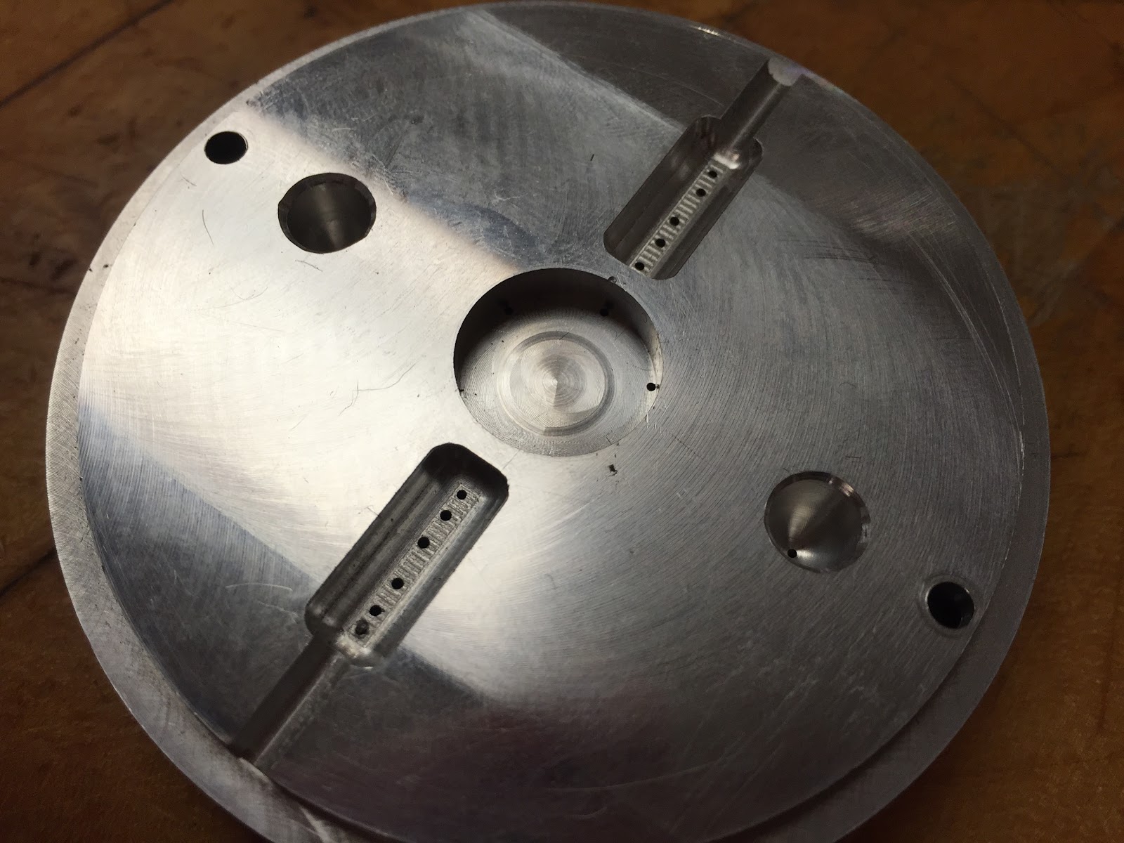
Since turning is faster than milling for equivalent quality of surface finish, any features of the molds that are rotationally symmetric were machined in the lathe. This meant all the features on the cavity and core were made in the lathe apart from the pockets and raised areas which generate the "islands" around the outside of the part. These islands, as well as the central large one, were initially given a 5 degree draft angle on the core mold to enable the part to be easily removed by the ejector pins. The ejector pin locations were chosen to be as uniformly distributed as was allowed by the shape of the core in order to spread the stress exerted on the plastic by the pins.
Alterations:
It was found in initial part manufacture that the the filling and cage did not fit together, as the "islands" were slightly too large. In order to fix this issue without having to remachine both the core and cavity molds of the filling, the part was simply made 0.015 inches thinner, which was decided to be a sufficient change based on measurements taken from the cage. This saved time and the parts now fit together well.
In addition, it was found that some cracking was occurring around the "island" features, an issue which will be discussed further under "process parameters". A 10 degree draft angle has subsequently been added to the islands on the core mold to allow easier removal of the part.
Process Plan:
Cavity
Step
|
Operation
|
Machine
|
Tool
|
Justification
|
1
|
Roughing Face
|
Lathe
|
1
|
Ensuring the mold has a flat front
surface
|
2
|
Roughing bore
|
Lathe
|
10
|
Remove a large amount of material
quickly from the cavity with a bore tool
|
3
|
Finishing bore
|
Lathe
|
5
|
Improve quality of surface finish
within the cavity
|
4
|
Pocketing
|
Mill
|
4
|
Pocket the “islands” in the cavity
(which cannot be lathed) with an endmill
|
Core
Step
|
Operation
|
Machine
|
Tool
|
Justification
|
1
|
Roughing of core shape
|
Lathe
|
1
|
Rapidly remove large amounts of
material from around the core mold
|
2
|
Finishing
|
Lathe
|
3
|
Improve the surface finish of the
main outline of the core
|
3
|
Rough trepan
|
Lathe
|
9
|
Create rough trepan feature
|
4
|
Trepan finishing (outer edge)
|
Lathe
|
8
|
Finishing pass along bottom and up
outer edge of trepan
|
5
|
Trepan finishing (inner edge)
|
Lathe
|
7
|
Finishing inner edge of trepan:
separate step necessary due to asymmetry of tools
|
6
|
Centre drill
|
Mill
|
13
|
Centre drill the ejector pin
locations to a depth of 0.1 inches
|
7
|
Peck Drill
|
Mill
|
17
|
Peck drill through the entire core to
create holes for ejector pins
|
8
|
Contouring (large tool)
|
Mill
|
4
|
Using large endmill to contour the
outline of the “islands” which cannot be lathed
|
9
|
Contouring (inside)
|
Mill
|
15
|
Put a 5 degree draft angle on the
inner edge of the “islands”
|
10
|
Contouring (outside)
|
Mill
|
16
|
Giving the outer edge of the
“islands” a 10 degree draft angle
|
Manufactured Molds:
Cavity

Core:

Process Parameters:
Finalized parameters:

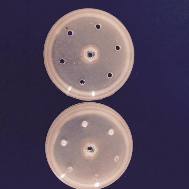
For the first part being made, conservative estimates were made, with lower injection and packing pressures and velocities, a shorter holding time and longer cooling time than shown above. The resulting parts had two main problems: short shot and cracking. One way the short shot was solved by gradually increasing injection pressure to 1600 psi, having started at 50, and the injection speed to 50% from the original 3%. Packing pressure rose from 50 to 900 psi and the hold time from 4 to 8 seconds. The shot size was increased from 18 mm to 25 mm. The net result of these iterative changes is shown below, with the progression of the part from severe short shot to being completely filled:

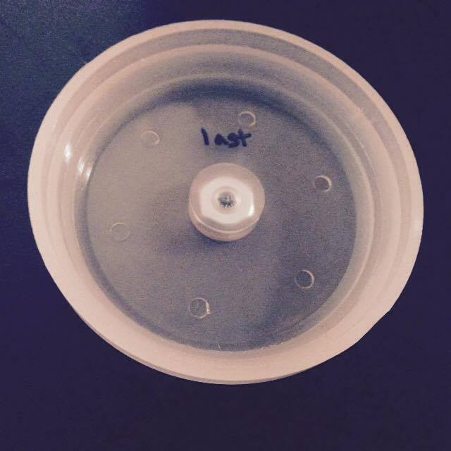
The cracking problem occurred because the islands of the core lacked draft angle on the outer edge. With the initially chosen cooling time of 25 seconds, this caused cracking not only around the islands but also in the inner area of the part around the ejector pins:

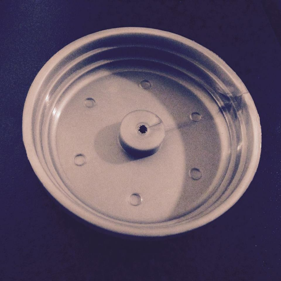
With the cooling time reduced to 15 seconds, the part was less tightly set around the core when ejected, so cracking was somewhat reduced. As shown below some minor cracks still appear around the islands, but the cooling time could not be lowered further without the plastic being soft enough to be damaged by the ejector pins.

In order to combat this problem, the core mold has subsequently been slightly re-machined with a 10 degree draft angle added around the outer edge of the "islands". This should enable the part to be ejected more easily and without cracking.
Component #1: Housing
The main thing the team learned during optimization was how to alter manufacturing parameters to eliminate various defects. Here are some defects we encountered, and our solutions:
Defect 1: Ejector Pin Holes
Solutions:
- Added another shim to make the ejector pins more flush with the part so that they would not poke through as much.
- Deburred the edges of our molds to make it easier to separate the part from the mold so that the mold no longer clings to the plastic.
Defect 2:Flash (excess material on edges of part)

Solution: Reduced the feed rate
Defect 3: Weld Lines (due to metallic silver color)
Solution: Kept the molds the way they are and dealt with the appearance of the metallic silver. The attractive color outweighed the unattractive weld line.
Defect 4: Loose Fitting and Little Plastic on Nut
Note: These were the most significant changes we had to make to ensure all four yoyo parts would fit together.
Solutions:
- Reduced the inner diameter of the housing core mold to ensure friction fit between the yoyo housing and cage.
- Deepened the nut pocket in the yoyo housing core mold to ensure that enough plastic would encase the nut.
Component #2: Cage
Defect 1: Burn mark

Solution:
- Reduced amount of plastic injected
- Drilled small hole in area of the mold where burning was happening to allow air to escape
Defect #2: Incomplete filling of part

Solution:
- Increased injection pressures so that plastic could fill the mold completely
Defect #3: Excess plastic

Solution:
- After part is injection molded, the excess plastic is cut off using diagonal cutting pliers
Defect #4: Weld Lines

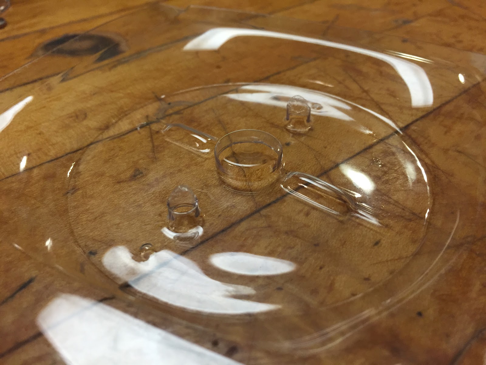
Componenet #3 - Thermoformed Electronics Holder
For the thermoforming process, the only parameters that were edited were heat time, cooling fan time, and vacuum time, as those parameters are the most critical to successful part formation. In the future other settings will be edited to increase production rate.
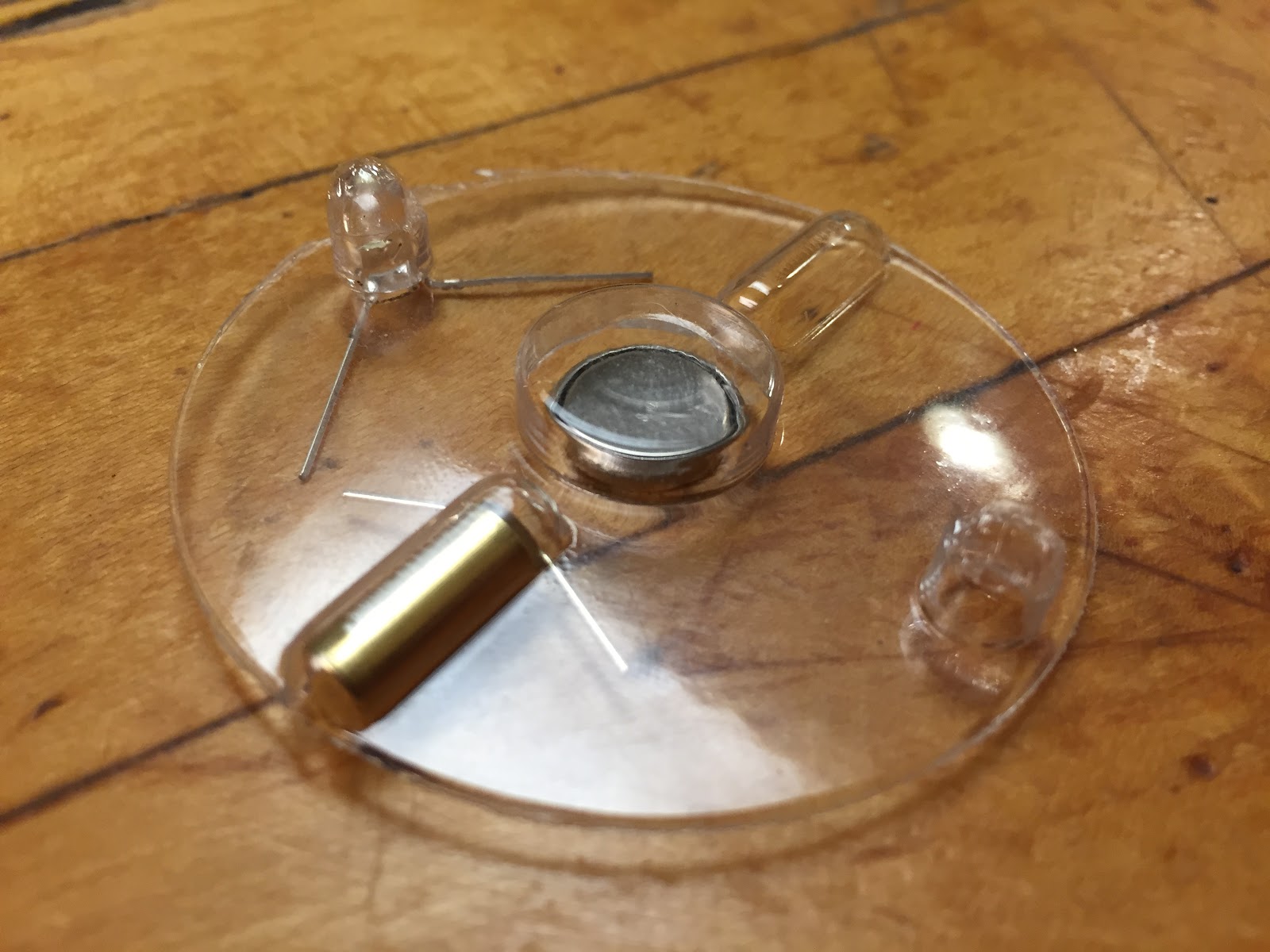
What I noticed following the first forming was that my part was larger than anticipated. The electronic components that were supposed to press-fit into the part were not held tightly, and simply fell out. Unfortunately, this immediately meant that I would have to re-machine the die. Despite this, I continued to adjust parameters to find an optimal balance to form my part. An issue that I noticed was an extremely thin material thickness at the bottom of the LED pocket (shown below). I attempted to increase heating time, to try and let the plastic flow easier into the cavity, but was unsuccessful. I then tried to chamfer the edge of the cavity to help plastic wrap around the edge better (shown below). This change appeared to help slightly, and I will re-machine the next die with a more aggressive chamfer.
Another error I spotted was a directional mistake of the alignment pins. Instead of having the plastic form over alignment pins, I will need to have it flow into a cavity, otherwise my thermoformed features will be destroyed by the die and punch used to cut out the part. This change was implemented manually, and allowed for correct part positioning in the punch and die. However, There was now insufficient vacuum pressure in the rest of the mold, since pressure was being lost to the newly made holes (shown below). To mitigate this, more vacuum holes were drilled in the other parts of the mold. Also, the correct size die that I was using was damaged, and thus unable to fully cut out my part.
Heating time proved to be a major factor in successful part formation. Too much (>50 sec) and the part warped severely when the die retraced at the end of the cycle. Too low (<30 sec) and the plastic did not form all the way into the part. Increasing cooling time helped mitigate warping. Increasing vacuum time helped plastic flow into difficult to reach areas, and helped increase material thickness at the bottom of the LED cavity slightly.
- Problem 1 - Incorrect pocket sizes
- Die must be re-machined to properly accommodate electronic components
- Problem 2 - Thin material at LED pockets
- Solution - Added chamfer to help plastic flow into cavity better
- Also increased heating time and vacuum time to increase flow
- Problem 3 - After inverting alignment pins to position in punch correctly, cavities were not forming properly due to low vacuum pressure.
- Solution - Added more vacuum holes

Additional work: The die needs to be re-machined to properly contain the electronics. In addition, the punch must be polished because it was not cutting out the part correctly. Thermoforming parameters will likely not have to be changed with the new die, but will be adjusted as needed.
No comments:
Post a Comment