Tuesday, December 8, 2015

Final Reflections

Summary Video
Click Here for our awesome video made by our very own Steven Gerasimoff!


Our yo-yo is inspired by the Arc Reactor that Tony Stark uses to power his suit and stay alive in the film Iron Man.The yoyo lights up when it spins so that it has the same glowing appearance as the reactor in the film.


Components/Key Features:
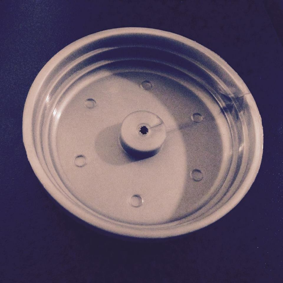
1. Housing (injection molded): houses all the yoyo components and has rounded edges for ergonomic and manufacturing benefits
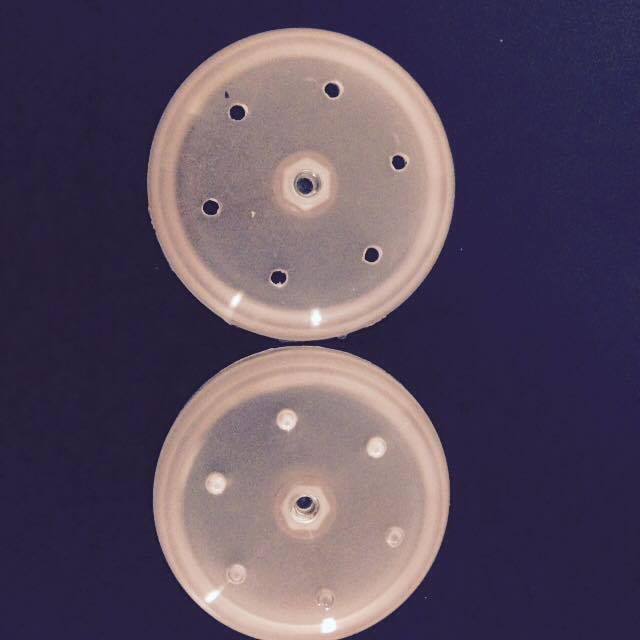
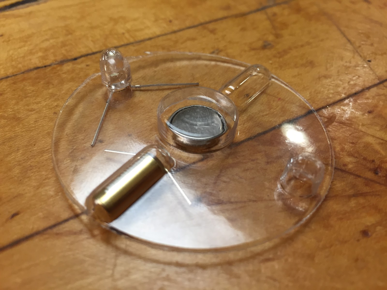
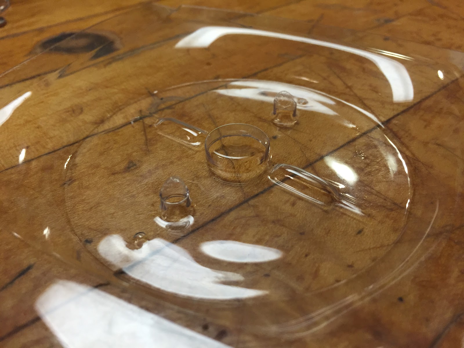
2. Circuit board holder (thermoformed) and circuit: consists of two LED lights, a coin battery, and two switches which allow the yoyo to light up when spinning. The battery was placed in the middle and the LEDs and switches on either side to ensure that the weight of our yo-yo is balanced around the center.


3. Filling (injection molded): fits into cage to produce patterned arc reactor image


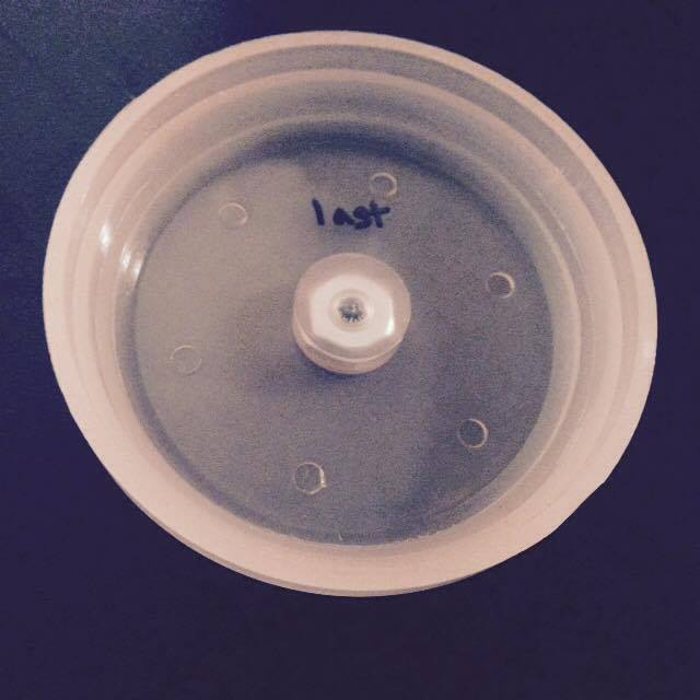
4. Cage (injection molded) provides the main image of the Arc Reactor while also fulfilling the function of friction fitting into the housing unit.
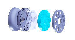
Exploded view of all parts.

Process Optimization:
To optimize the manufacturing parameters for the injection molded and thermoformed parts, we went through an iterative design process in which we observed defects in parts and altered parameters closely linked to that defect until we were satisfied with our yoyo prototype (specific examples are in the previous blog post).

Successes: 
Overall we're happy with our yoyo! All the parts snap fit together well, and the yoyo looks is visually appealing especially when it lights up!

Opportunities for Improvement:
1. Make more robust and durable circuits by using better wires/soldering 
2. Make battery easier to change (more maintainable yoyo) by increasing housing diameter slightly to enable a looser snap fit
3. Make the yoyo smaller so it fits in one's hands easier.
4. Another weakness is that the process capability of the critical dimensions of the yoyo are quite low. This could be due to a number of reasons including the  deliberate introduction of a step change of one process parameter mid way through the production run, and the machine errors because of age and use.


Comparison to FDM parts:


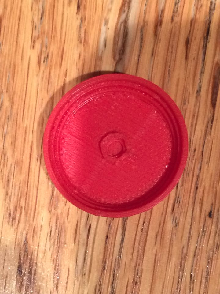
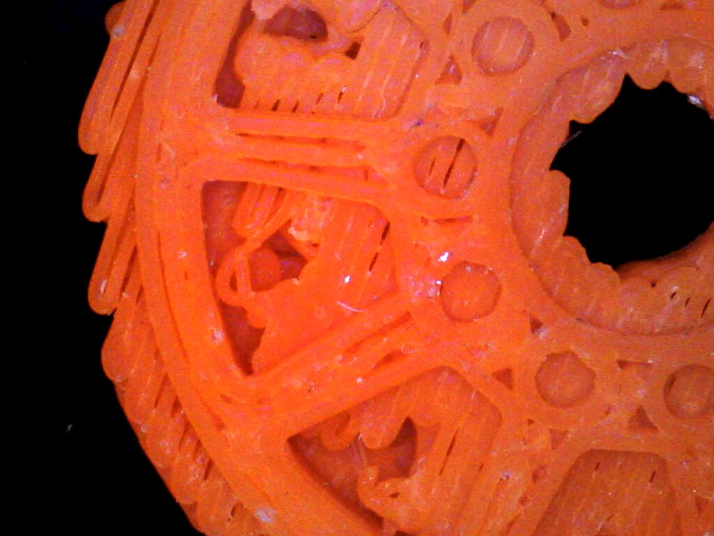
Our group used FDM to prototype both our yoyo housing and cage (as pictured below). Manufacturing these parts helped us verify that our part would be aesthetically pleasing, but because we could not completely remove the raft from the parts, we were not able to test that the parts fit together by friction fitting. The resolution of the UP! FDM printer that we used was low (best resolution/layer thickness of .2mm), so this caused the intricate detailing and geometry present on the cage to not be as clear as it appears on our final injection molded parts. Also the low resolution contributed to the surface of the FDM pieces having visible lines and a rough surface finish. The injection-molded yoyo cage and housing have a much smoother surface finish.  


Design Specification Comparison


Quantity
Design Specification
Tolerance
Mean Measurement
Description
String Gap
0.075 in
+/- 0.015
.125 in
This dimension was wider than expected possibly because the screw holding the two yoyo halves together was longer than expected. The large string gap caused slippage to occur making it hard to return yoyo to hand so we double looped the string hole around the axle to fix this issue.
Housing Inner Diameter
2.346 in
+/- 0.015
2.345 in
The measurement meets the target since it’s within the tolerance. It meets the target because shrinkage was taken into account when designing the mold to ensure that part would shrink to the right ID.
Filling Outer Diameter
2.180 in
+/- 0.015
2.198 in
Although the shrinkage was overestimated such that the final parts were larger than expected, they fit well with the cage and housing so were not altered.
Circuit Holder Outer Diameter
2.17 in
+/- 0.01
2.170 in
Dimension determined by the size of the punch used. Criteria was met because of the precision of the punch.
Cage Outer Diameter
2.350 in
+/- 0.01
2.349 in
This dimension met the target because shrinkage was taken into account when designing the mold to ensure that part would shrink to the right OD.
Total Mass
68g
N/A
59.4g
Total mass of fully assembled yoyo. Volume of plastic used was different.
Rotation Speed
942 rpm
N/A
1015 rpm
Measured with optical tachometer. Yoyo was dropped, not thrown. Calculation was close to the measured value, indicating adequate assumptions and measurement.


Note: Since all of our parts fit together, we would use the mean measured specifications above for mass production of the yoyos. The only change would be to narrow the string gap to original design specification of .075 in +/- .015 in so that double looping of string isn’t needed and assembly time is decreased.

Cost Analysis for Prototyping Versus Mass Production Summary


                                                                                                                                                        The above graph shows the variation of unit cost against production volume for 3 different production methods. These 3 are the 2.008 prototyping method, additive manufacturing and high volume. The additive manufacturing cost estimates were made using quotes from Fineline Prototyping for the plastic parts of the yo-yos. The approximations used for modelling high volume production costs included decreased unit run time due to multi-cavity and molds and decreased material costs resulting from large bulk orders. For very low volume production, additive manufacturing is cheapest, but for volumes greater than 10 yo-yos, 2.008 methods become the lower cost option. High volume methods prove far cheaper for volumes where these become feasible, generally for runs of >5000 yo-yos. These unit costs can be broken down into material, tooling, equipment and overhead cost, as shown in the following table:


Production Run
Total Unit Cost
Materials
Tooling
Equipment
Overhead
50 yo-yos, 2.008 methods
90.42
7.1
46
2.33
35
50 yo-yos, AM
113.19
78.19
35
0
0
100000 yo-yos (high volume)
7.95
2.46
0.02
0.04
5.43

                                                                                                                                       This table shows that tooling and overheads dominate for 2.008 prototyping at low volumes, whereas material costs (i.e. the cost of purchasing printed parts from an external manufacturer) are more important in AM. At very high volumes, overheads and material costs (i.e. variable costs) dominate the price of production.                                                                                                                                                                                                                                                                                                                                                                                                                                                                                                                                                                                                                                     
YY Design and the Constraints of 2.008
Our yoyo naturally fell within most of the constraints of the 2.008 lab. However one thing we could change for mass production is to use side-action on the injection molded molds. This would have allowed us to have less of a visible weld line (present on the silver injection molded parts: cage and housing). We would have also used an injection molding machine that can make multiple parts at a time. The molds could also have more cavities. Another change is that we would have used better quality wire so that the circuits are more durable/robust.

Friday, November 20, 2015

A Reflection on the Process Optimization Process


In-depth Component Description (Filling):


Design:


The molds for the filling were designed using Solidworks Plastics, as shown below. The main consideration that had to be made was shrinkage, which was estimated to be 2% based on molds and their corresponding components from previous years. As such, the part used to design the molds in Solidworks was increased in size of 2%.


The choice of parting surface was fairly arbitrary since the entire outer edge of the part will be inside the yo-yo housing and need not therefore avoid having a sharp edge at the parting line. The line chosen was at the base of the outer edge for ease of mold machining.


Mold Manufacture:

Initial:
Since turning is faster than milling for equivalent quality of surface finish, any features of the molds that are rotationally symmetric were machined in the lathe. This meant all the features on the cavity and core were made in the lathe apart from the pockets and raised areas which generate the "islands" around the outside of the part. These islands, as well as the central large one, were initially given a 5 degree draft angle on the core mold to enable the part to be easily removed by the ejector pins. The ejector pin locations were chosen to be as uniformly distributed as was allowed by the shape of the core in order to spread the stress exerted on the plastic by the pins.
Alterations:
It was found in initial part manufacture that the the filling and cage did not fit together, as the "islands" were slightly too large. In order to fix this issue without having to remachine both the core and cavity molds of the filling, the part was simply made 0.015 inches thinner, which was decided to be a sufficient change based on measurements taken from the cage. This saved time and the parts now fit together well.
In addition, it was found that some cracking was occurring around the "island" features, an issue which will be discussed further under "process parameters". A 10 degree draft angle has subsequently been added to the islands on the core mold to allow easier removal of the part.

Process Plan:


Cavity

Step
Operation
Machine
Tool
Justification
1
Roughing Face
Lathe
1
Ensuring the mold has a flat front surface
2
Roughing bore
Lathe
10
Remove a large amount of material quickly from the cavity with a bore tool
3
Finishing bore
Lathe
5
Improve quality of surface finish within the cavity
4
Pocketing
Mill
4
Pocket the “islands” in the cavity (which cannot be lathed) with an endmill

Core

Step
Operation
Machine
Tool
Justification
1
Roughing of core shape
Lathe
1
Rapidly remove large amounts of material from around the core mold
2
Finishing
Lathe
3
Improve the surface finish of the main outline of the core
3
Rough trepan
Lathe
9
Create rough trepan feature
4
Trepan finishing (outer edge)
Lathe
8
Finishing pass along bottom and up outer edge of trepan
5
Trepan finishing (inner edge)
Lathe
7
Finishing inner edge of trepan: separate step necessary due to asymmetry of tools
6
Centre drill
Mill
13
Centre drill the ejector pin locations to a depth of 0.1 inches
7
Peck Drill
Mill
17
Peck drill through the entire core to create holes for ejector pins
8
Contouring (large tool)
Mill
4
Using large endmill to contour the outline of the “islands” which cannot be lathed
9
Contouring (inside)
Mill
15
Put a 5 degree draft angle on the inner edge of the “islands”
10
Contouring (outside)
Mill
16
Giving the outer edge of the “islands” a 10 degree draft angle


Manufactured Molds:

Cavity

Core:


Process Parameters:
Finalized parameters:

How these parameters were reached:

For the first part being made, conservative estimates were made, with lower injection and packing pressures and velocities, a shorter holding time and longer cooling time than shown above. The resulting parts had two main problems: short shot and cracking. One way the short shot was solved by gradually increasing injection pressure to 1600 psi, having started at 50, and the injection speed to 50% from the original 3%. Packing pressure rose from 50 to 900 psi and the hold time from 4 to 8 seconds. The shot size was increased from 18 mm to 25 mm. The net result of these iterative changes is shown below, with the progression of the part from severe short shot to being completely filled:

The cracking problem occurred because the islands of the core lacked draft angle on the outer edge. With the initially chosen cooling time of 25 seconds, this caused cracking not only around the islands but also in the inner area of the part around the ejector pins:


With the cooling time reduced to 15 seconds, the part was less tightly set around the core when ejected, so cracking was somewhat reduced. As shown below some minor cracks still appear around the islands, but the cooling time could not be lowered further without the plastic being soft enough to be damaged by the ejector pins.


In order to combat this problem, the core mold has subsequently been slightly re-machined with a 10 degree draft angle added around the outer edge of the "islands". This should enable the part to be ejected more easily and without cracking.


Component #1: Housing
The main thing the team learned during optimization was how to alter manufacturing parameters to eliminate various defects. Here are some defects we encountered, and our solutions:


Defect 1: Ejector Pin Holes
Solutions:
  • Added another shim to make the ejector pins more flush with the part so that they would not poke through as much.
  • Deburred the edges of our molds to make it easier to separate the part from the mold so that the mold no longer clings to the plastic.


Defect 2:Flash (excess material on edges of part)
Solution: Reduced the feed rate


Defect 3: Weld Lines (due to metallic silver color)


Solution: Kept the molds the way they are and dealt with the appearance of the metallic silver. The attractive color outweighed the unattractive weld line.


Defect 4: Loose Fitting and Little Plastic on Nut
Note:  These were the most significant changes we had to make to ensure all four yoyo parts would fit together.
Solutions:

  • Reduced the inner diameter of the housing core mold to ensure friction fit between the yoyo housing and cage.
  • Deepened the nut pocket in the yoyo housing core mold to ensure that enough plastic would encase the nut.

Component #2: Cage

Defect 1: Burn mark
Solution:
  • Reduced amount of plastic injected
  • Drilled small hole in area of the mold where burning was happening to allow air to escape
Defect #2: Incomplete filling of part
Solution:
  • Increased injection pressures so that plastic could fill the mold completely
Defect #3: Excess plastic
Solution:
  • After part is injection molded, the excess plastic is cut off using diagonal cutting pliers
Defect #4: Weld Lines
We decided to have a silver color for our yoyo
Componenet #3 - Thermoformed Electronics Holder

For the thermoforming process, the only parameters that were edited were heat time, cooling fan time, and vacuum time, as those parameters are the most critical to successful part formation. In the future other settings will be edited to increase production rate.
What I noticed following the first forming was that my part was larger than anticipated. The electronic components that were supposed to press-fit into the part were not held tightly, and simply fell out. Unfortunately, this immediately meant that I would have to re-machine the die. Despite this, I continued to adjust parameters to find an optimal balance to form my part. An issue that I noticed was an extremely thin material thickness at the bottom of the LED pocket (shown below). I attempted to increase heating time, to try and let the plastic flow easier into the cavity, but was unsuccessful. I then tried to chamfer the edge of the cavity to help plastic wrap around the edge better (shown below). This change appeared to help slightly, and I will re-machine the next die with a more aggressive chamfer.
Another error I spotted was a directional mistake of the alignment pins. Instead of having the plastic form over alignment pins, I will need to have it flow into a cavity, otherwise my thermoformed features will be destroyed by the die and punch used to cut out the part. This change was implemented manually, and allowed for correct part positioning in the punch and die. However, There was now insufficient vacuum pressure in the rest of the mold, since pressure was being lost to the newly made holes (shown below). To mitigate this, more vacuum holes were drilled in the other parts of the mold. Also, the correct size die that I was using was damaged, and thus unable to fully cut out my part.
Heating time proved to be a major factor in successful part formation. Too much (>50 sec) and the part warped severely when the die retraced at the end of the cycle. Too low (<30 sec) and the plastic did not form all the way into the part. Increasing cooling time helped mitigate warping. Increasing vacuum time helped plastic flow into difficult to reach areas, and helped increase material thickness at the bottom of the LED cavity slightly.

  • Problem 1 - Incorrect pocket sizes
  • IMG_0105.JPG
    • Die must be re-machined to properly accommodate electronic components
  • Problem 2 - Thin material at LED pockets
  • IMG_0106.JPG
    • Solution - Added chamfer to help plastic flow into cavity better
    • Also increased heating time and vacuum time to increase flow 
  • Problem 3 - After inverting alignment pins to position in punch correctly, cavities were not forming properly due to low vacuum pressure.
    • Solution - Added more vacuum holes
IMG_0107.JPGIMG_0108.JPG
Additional work: The die needs to be re-machined to properly contain the electronics. In addition, the punch must be polished because it was not cutting out the part correctly. Thermoforming parameters will likely not have to be changed with the new die, but will be adjusted as needed.